

Introduction
In our previous post on platform security (see here) we provided a brief introduction into platform security protections on AMD-based platforms and touched upon the topic of AMD Platform Secure Boot (PSB).
As a quick reminder, the purpose of PSB is to provide a hardware root-of-trust that will verify the integrity of the initial UEFI firmware phases, thereby preventing persistent firmware implants.
In this part of the blog series, we will dig deeper into the nitty gritty details of PSB, including a first glimpse of how it works under the hood, how it should be configured and, naturally, how various major vendors fail to do so.
Architecture
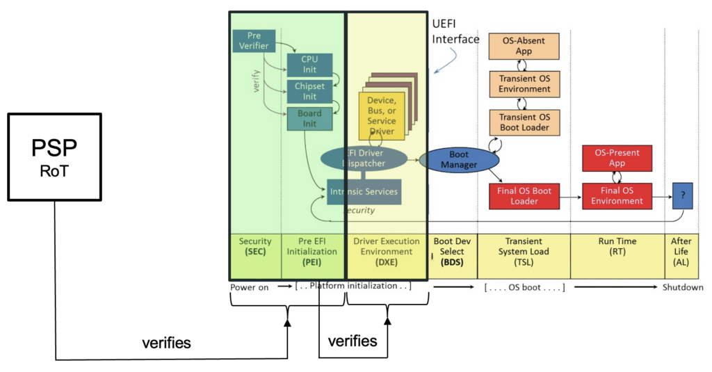
To begin, it is important to understand that the UEFI boot process is divided into various phases, referred to as SEC, PEI, DXE, BDS, TSL, RT and AL. For the sake of brevity, we won’t go into detail on the purpose of each phase as it has already been widely covered already (e.g. here).
In short, the role of the PSB is to ensure that the initial UEFI phases, specifically the SEC and PEI phase, are properly verified and cannot be tampered with. In turn, the PEI phase will verify the DXE phase using a proprietary and vendor-specific method.
The resulting scheme is summarized in the following image:
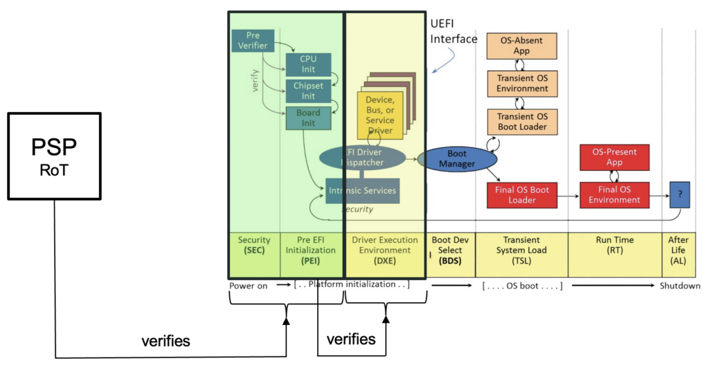
Upon reset, only the AMD Platform Security Processor (PSP), an ARM-based co-processor embedded within the AMD chip, is running. It functions as a hardware root-of-trust and verifies the SEC and PEI phase portions of the UEFI firmware. If verification succeeds, then it releases the main cores that then start executing the SEC and PEI phase.
Trust Hierarchy
In order to understand the trust hierarchy in more depth, we will first take a look at how the UEFI firmware, stored in the SPI flash, is structured. To do so, we will use the SPI flash dump we have obtained from an AMD-based Huawei Matebook 16 (BIOS v2.28).
When we open up a SPI flash dump with our trusty UEFI Tool, we will typically see, among others, the following structures:
- Padding areas
- Firmware volumes (containing DXE drivers and SMM modules)
- NVRAM data (containing non-volatile configuration data, i.e. UEFI variables)
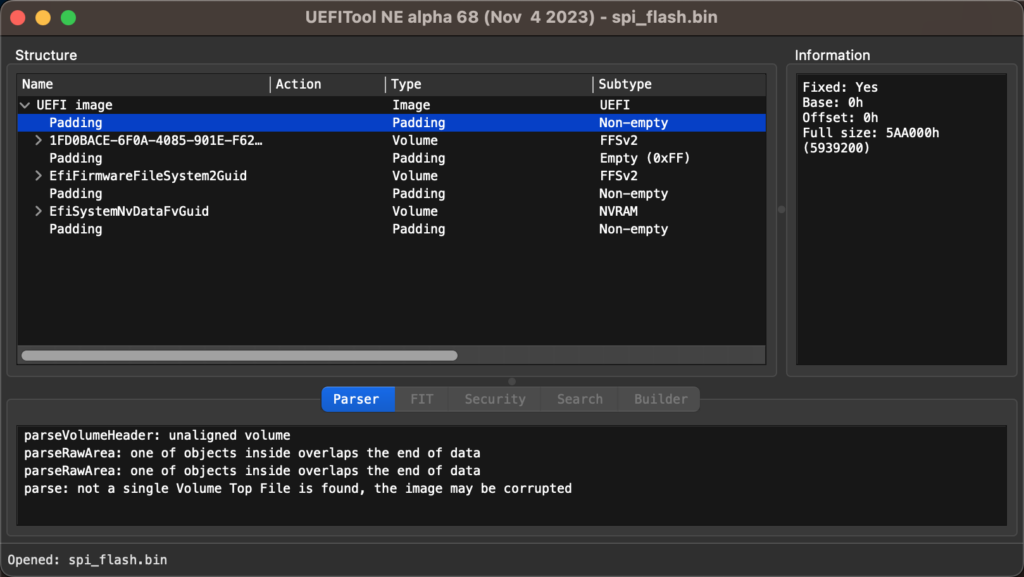
However, while UEFI Tool correctly identifies firmware volumes that contain code executed in the DXE phase of the UEFI boot process, the code running in the SEC and PEI phases seems to be missing altogether.
This is because it does not support parsing an AMD platform specific structure called the Embedded Firmware Structure (EFS). Once again, for the sake of brevity, as the structure is relatively complex, we will only focus on portions relevant to the chain-of-trust.
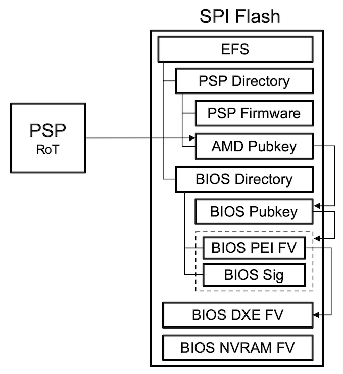
As described here, the EFS is located at one of the pre-defined locations in the SPI flash and contains pointers to:
- The PSP directory table that includes: The BIOS signing key (entry type 0x05)
- The BIOS PEI firmware volume (entry type 0x62)
- The BIOS PEI firmware volume signature (entry type 0x07)
- The AMD root signing key (entry type 0x00)
In visualized form, the resulting data structure looks as follows:
As a sidenote, we have also developed a simple parser (available here) that can be used to parse and extract the different portions of the PSP and BIOS directories.
Upon reset, the PSP will hold the main cores and verify the trust chain in the following order:
- The AMD root signing key is verified against a SHA256 hash programmed into the PSP
- The BIOS signing key is verified against the AMD root signing key
- The BIOS PEI firmware volume is verified against the BIOS signing key
At this point the PSP releases the main cores and the SEC+PEI phase code, stored in the PEI firmware volume, will execute. Then, to complete the chain-of-trust, a vendor-specific PEI module will verify the DXE firmware volume(s).
PSB Configuration
The next step is to understand how we can interact with the PSP to determine whether the PSB is properly configured or not. This, in turn, could be used to implement a simple tool to detect potential misconfigurations.