

Several weeks ago, international regulators announced that they were ordering Boeing 787 operators to completely shut down the plane’s electrical power whenever it had been running for 51 days without interruption.1 The FAA published an airworthiness directive elaborating on the issue, and I was curious to see what kind of details were in this document.
While I eventually discovered that there wasn’t much information in the FAA directive, there was just enough to put me on track to search for the root cause of the issue. This blog post will leverage the interesting bits of information in the FAA directive to gain knowledge about some avionics concepts.
First, we need to introduce the parts of the 787’s architecture and systems that are relevant to this issue. The FAA directive explicitly uses acronyms, such as CDN or CCS, that need to be defined before moving to root cause analysis.
What is the Common Core System (CCS)?
As opposed to the federated avionics architectures, which make use of distributed avionics functions that are packaged as self-contained units, Integrated Modular Avionics (IMA)2 architectures employ a high-integrity, partitioned environment that hosts multiple avionics functions of different criticalities on a shared computing platform. Boeing engineers went one step further and developed the Common Core System (CCS) for the 787, a further enhancement based on an open IMA avionics technology.
Essentially the CCS is a hardware/software platform that provides computing, communication, and input-output (I/O) services for implementing real-time embedded systems, known as hosted functions.
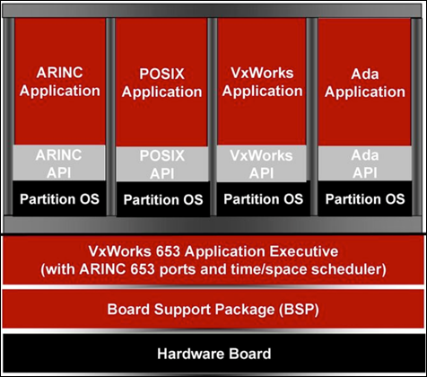
Multiple hosted functions share the platform resources within a virtual system environment enforced by partitioning mechanisms that are implemented as part of the platform design, relying on a VxWorks 6533,4 OS.5
This virtual system partitioning environment guarantees that hosted functions are isolated from each other, so it supports highly critical applications but also lower levels of application integrity. Remember that international regulations define five levels of failure conditions, categorized by their effects on the aircraft, crew, and passengers:
Level A–Catastrophic
Failure may cause multiple fatalities, usually with loss of the airplane.
Level B–Hazardous
Failure has a large negative impact on safety or performance, reduces the ability of the crew to operate the aircraft due to physical distress or a higher workload, or causes serious or fatal injuries among the passengers.
Level C–Major
Failure significantly reduces the safety margin or significantly increases crew workload. May result in passenger discomfort (or even minor injuries).
Level D–Minor
Failure slightly reduces the safety margin or slightly increases crew workload. Examples might include causing passenger inconvenience or a routine flight plan change.
Level E–No Effect
Failure has no impact on safety, aircraft operation, or crew workload.
Software approved to levels A, B, or C requires strong certification involving formal processes for verification and traceability
As a result, a DO-178B6 Level-A software may coexist in the same physical shared resource with a Level-E application.
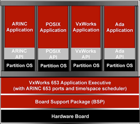
Ideally, the applications cannot interfere with each other, regardless of faults that may occur within the hosted functions or the platform resources, which are predetermined and communicated to the platform components via loadable configuration files usually in either XML or proprietary binary formats.
Within the CCS we can find the following major components:
- General Processing Modules (GPMs) to support functional processing needs
- Remote Data Concentrators (RDCs) to support system analog signals, analog discrete signals, and serial digital interfaces (CAN bus8, A4299, etc.)
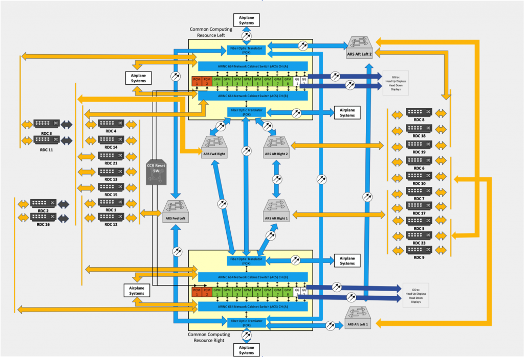
- Avionics Full Duplex (A664-P7) Switched Ethernet10 network for communication between platform elements
These elements can be packaged as Line Replaceable Units (LRUs)11 or in module or card form, which can then be grouped within cabinets or integrated LRUs. As a result, the CCS is made up of:
- Two (2) Common Computing Resource (CCR) cabinets
- The Common Data Network (CDN)
- 21 RDCs
Common Computing Resource Cabinets
Each CCR cabinet has:
- Two (2) Power Conditioning Modules (PCMs)
- Eight (8) General Processing Modules (GPMs)
- Two (2) ARINC 664-P7 network Cabinet Switches(ACSs)
- Two (2) Fiber Optic Translator Modules (FOXs)
- Two (2) Graphic Generators (part of the Displayand Alert Crew System)
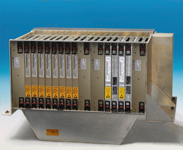
Each GPM is an independent computing platform that hosts airplane systems’ operational software and provides the hosted applications a partitioned environment based on the ARINC 653 standard. Each GPM has the same hardware and core operating system.
The GPMs in these CCR cabinets run hosted functions such as Remote Power Distribution System (RPDS), Generator/Bus Power Control Unit (GCU/BPCU),13 Circuit Breaker Indication and Control, Landing Gear Indication and Control, Thrust Management Function, and Flight Management Function.